So analogue is not dead yet
Mark


I prefer modding pin 9 as this is easy, remove C2 and R6. Solder a piece of wire between the negative pole of C2 and the "right" side of the resistor and the mod is ready without cutting traces. So it's quite reversible.This only possible problem with using PL4 is there are really only 4 easily usable free pins driven from the 6847 (OA, OB, CB and HS). We need one more for VGA, which would mean a mod to free up pin 9, or putting a VGA VSync out in place of the Atom FS. Any idea how sensitive software on the Atom is to the duration of FS (on the 6847 it is ~2ms and on VGA it is much shorter, 128us I think).
If I re-purposed FS as VGA VSync, it would still have a period of 60Hz. The only difference is that the width of the low pulse ~128us vs ~3ms. I think the WAIT routine at FE66 would work just the same. I might give it a try.roland wrote:Hi Dave,
FS is often used in programs because of its constant timing. It's a 60Hz signal (which makes the duration ~16 ms) and many games use this signal for delaying. Also some sound statements use it. I suggest to keep this signal as is.
I've just had a quick scan of that data sheet, and it implies that the intended RF output is on Ch3 or Ch4, so between 60MHz and 70MHz. So you'd need a VHF NTSC set. Adjustable via the tank circuit on pins 13/14, but I doubt that it'll work at UHF (CH21 starts at 470MHz). Also remember that NTSC as broadcast normally uses +ve modulation, rather than -ve modulation as was used for PAL on UHF in the UK.hoglet wrote:On ebay:
http://www.ebay.com/itm/Vintage-Acorn-A ... 1713196396
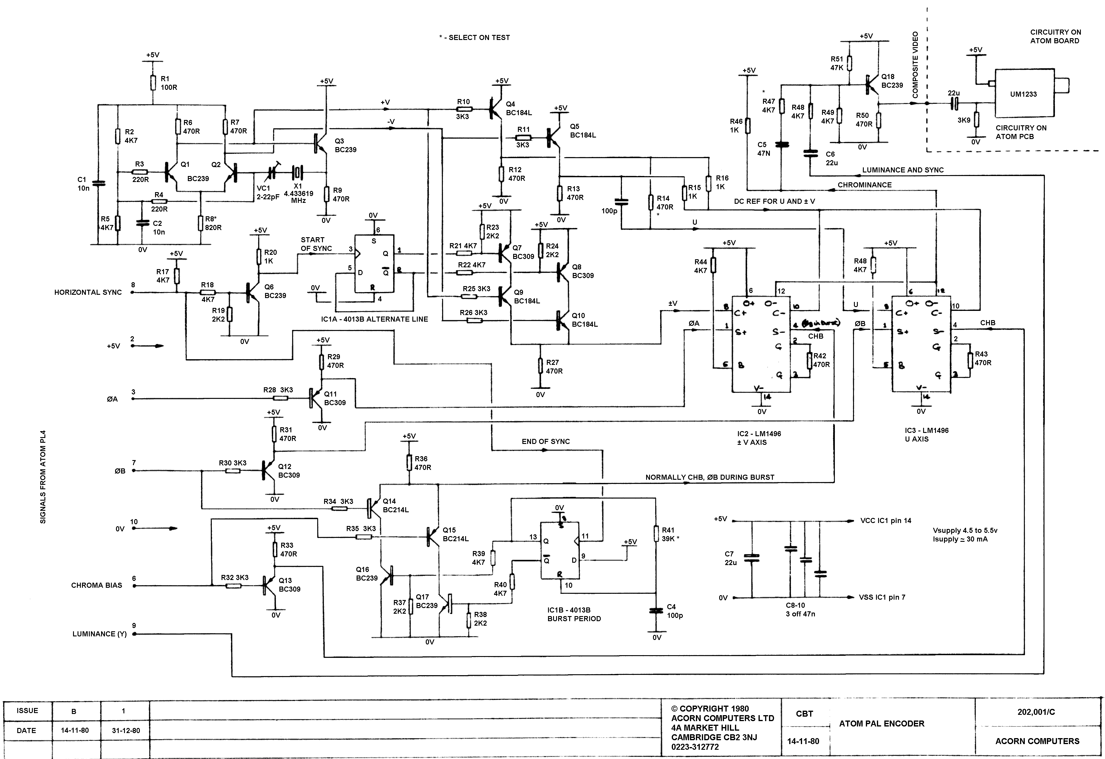
This expensive Atom has a colour board I have not seen before: Can anyone identify what this is?
The MC1372 is a colour modulator designed to work with the MC6847: The MC1372P is available on eBay, so I'm going to try and make one of these I think for my original Atom.
Dave
Oh right, I should have read it more thoroughly before posting. Plus checking ebay they are only a couple of quid so I might get a couple myself, I'd assumed they would be @@@@@RARE@@@@@@.hoglet wrote:Hi Phil,
I think it's possible to use the MC1372 to generate baseband composite video. In the data sheet Test Circuit 2 does this.
There are also a family of composite video boards for the CoCo2 that use the MC1372. See this page for more details:
https://sites.google.com/site/thezippst ... 2-projects
There are some screen shots and the quality looks quite good.
Dave
What, on a composite output, neverhoglet wrote:... the picture is very soft and fuzzy.
Gosh that was a long time ago!trixster wrote:Dave, in the GBS post on page one of the thread you mention tweaking the GBS to get it to output 50hz rather than 60hz. Is this a simple thing to do or did you have to hack the firmware?


