aerworuld wrote:Prime wrote:As Arcadian has some blank PCBs, if he can get a couple to me, and someone can do a close up shot of the board so I can see what chips go where, I could try tracing a schematic for it....which is *MUCH* easier to do with a blank board

Phill, I've bought 2 boards from Dave so that I have a spare in case I mess up; I would be happy to send one over if it would help with schematic production?
Stuart
You could also pop a blank board in a scanner, (both sides), then post a link to the images produced...

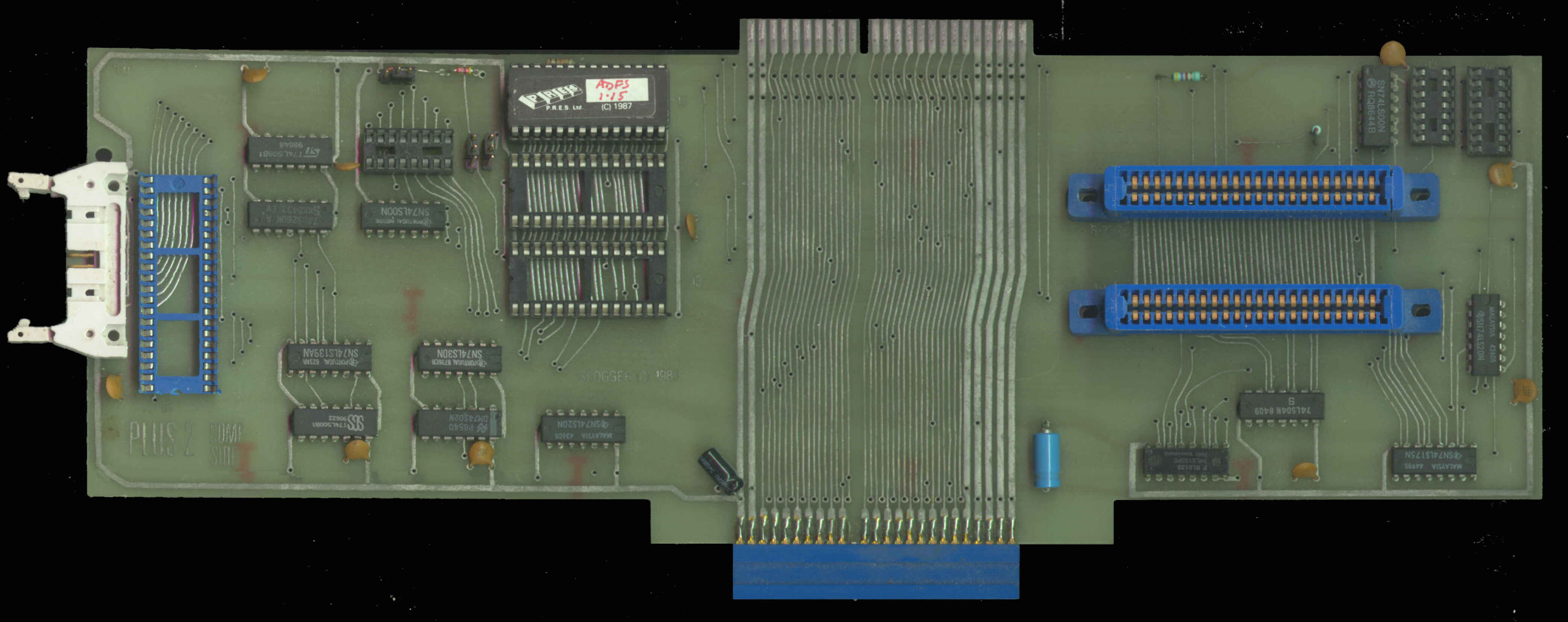
There are four empty sockets on the picture of the board you linked to.
One is a blue 40 pin socket for a 6522 VIA to provide the "USER" port. One is a 14 pin socket (most likely for a "TTL" logic chip).
That leaves two, both 16 pin sockets. Now, I cannot think of a serial port UART / ACIA / SCI that fits a 16 pin socket (remember it needs 2 power pins, 8 pins for the data bus, a chip select, a write control, at least one address/register control input, a clock input, a "RX" serial input and a "TX" serial output (and that's not taking into account RTS and CTS). If you have a look at the data sheet for the MC6850 ACIA you will see that it comes in a 24 pin DIL package.
A line driver chip is also needed. And of course, a lot of "TTL" logic chips also come in 16 pin DIL packages.
So it may be that adding the serial port on this board is not a simple as was hoped

.
If I were to speculate, I would suggest that either the serial port uses the serial-parallel shift registers in the 6522 VIA, or it uses a "TTL" logic chip to do the same, or it is a bit-bashed serial port. See
here for UART / ACIA / SCI info
Hmm, more of a mystery, more questions...
 Mark
Mark


