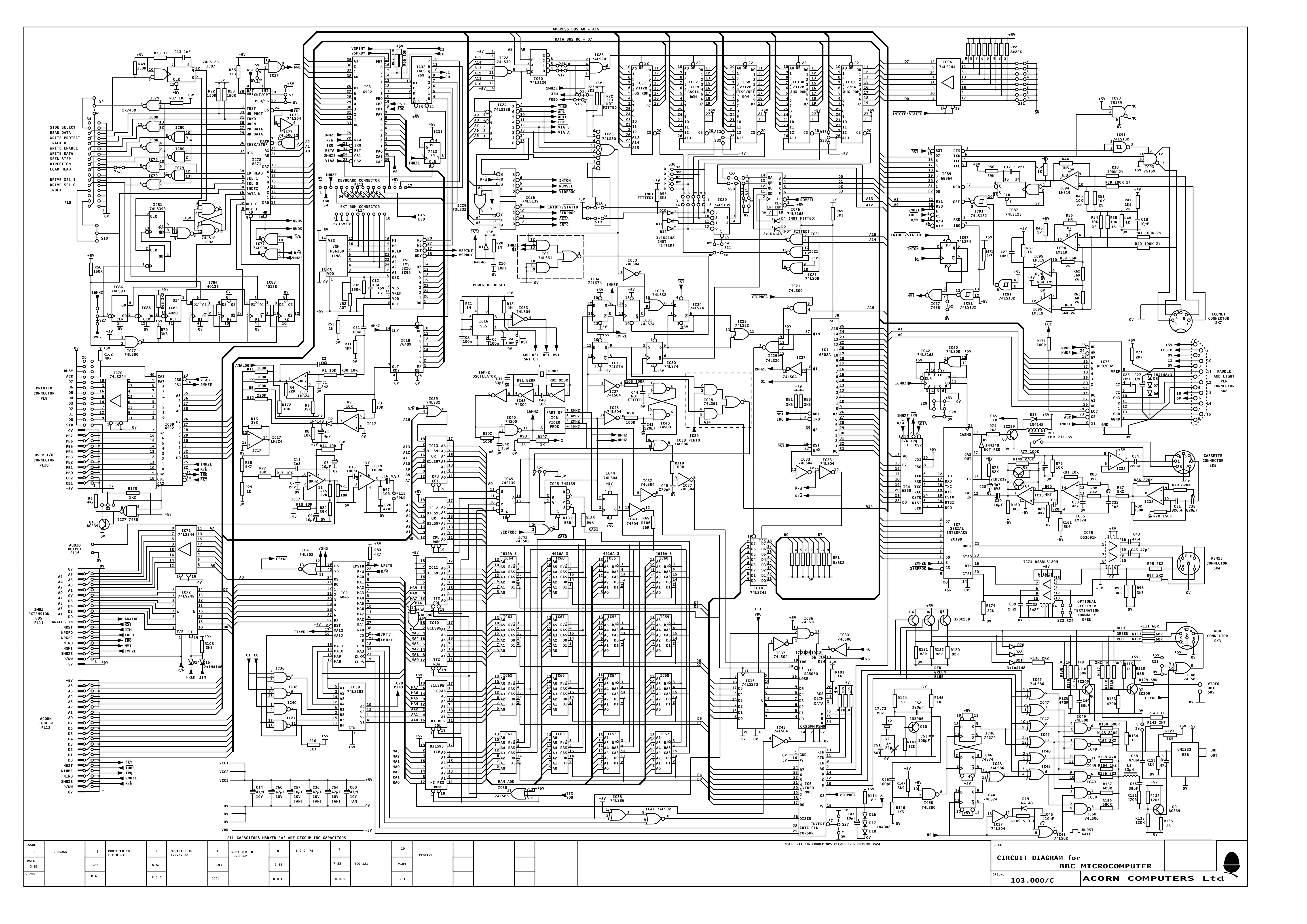
Most of the circuit diagrams I've found on the web are not very clear.
Found an original diagram so scanned it in. Hope this is of use to someone.
BBC Circuit diagram
-
JannievanZyl
- Posts: 232
- Joined: Sat Feb 11, 2017 8:56 pm
- Location: Cape Town, South Africa
- Contact:
Re: BBC Circuit diagram
That's the best scan of an original I've seen on the web, thank you.
I've been making use of a (digitally) redrawn diagram hosted on 8BS.
I've been making use of a (digitally) redrawn diagram hosted on 8BS.
BBC Model B 32K issue 7, Sidewise ROM board with 16K RAM
Archimedes 420/1 upgraded to 4MB RAM, ZIDEFS with 512MB CF card
RiscPC 600 under repair
Acorn System 1 home-made replica
Archimedes 420/1 upgraded to 4MB RAM, ZIDEFS with 512MB CF card
RiscPC 600 under repair
Acorn System 1 home-made replica
Re: BBC Circuit diagram
Yes good scan. I've been using the tribbeck one but not on its own because it has errors... some pin numbers and IC numbers are wrong. Can't remember which ones off the top of my head.Kazzie wrote:That's the best scan of an original I've seen on the web, thank you.
I've been making use of a (digitally) redrawn diagram hosted on 8BS.
-
JannievanZyl
- Posts: 232
- Joined: Sat Feb 11, 2017 8:56 pm
- Location: Cape Town, South Africa
- Contact:
Re: BBC Circuit diagram
Cool, I literally just scanned it first pass. Shows how good the scanners have become. This was an HP7612.
-
1024MAK

- Posts: 12780
- Joined: Mon Apr 18, 2011 5:46 pm
- Location: Looking forward to summer in Somerset, UK...
- Contact:
Re: BBC Circuit diagram
I often use the one from here, mainly because I have bookmarks on most of my devices / computers to this page...
But I welcome any good quality scans of schematic drawings
Mark
But I welcome any good quality scans of schematic drawings
Mark
For a "Complete BBC Games Archive" visit www.bbcmicro.co.uk NOW!
BeebWiki - for answers to many questions...
Fault finding index • Acorn BBC Model B minimal configuration • Logic Levels for 5V TTL Systems
BeebWiki - for answers to many questions...
Fault finding index • Acorn BBC Model B minimal configuration • Logic Levels for 5V TTL Systems
-
DutchAcorn

- Posts: 2674
- Joined: Fri Mar 21, 2014 9:56 am
- Location: Maarn, Netherlands
- Contact:

Re: BBC Circuit diagram
Thanks that is much better than the one that I got with my beeb.
Re: BBC Circuit diagram
That's the same as BBCBschematicJTribbeck.png that kazzie linked to. That's the one that has some errors.DutchAcorn wrote:This one is my favorate:
BBC B schematics clean.png
-
dominicbeesley

- Posts: 2210
- Joined: Tue Apr 30, 2013 12:16 pm
- Contact:
Re: BBC Circuit diagram
Ooh that's much clearer than the one I've been using. Where did you source the hard copy?
PS: thanks for sharing!
PS: thanks for sharing!
-
dominicbeesley
- Posts: 2210
- Joined: Tue Apr 30, 2013 12:16 pm
- Contact:
Re: BBC Circuit diagram
I'm still interested where you got this from Jannie,
I've spotted some differences to my "canonical" one (103,000/C of Issue 9 7/83) it would be good to know any information that could date it.
(I've not looked hard, but just now I spotted D4/D5 specified as not fitted on the issue 9 diagram but no note on Jannie's diagram).
Does anyone know if D4/D5 were ever fitted, I can't see there being much point other than maybe a boot up check?
D
-
JannievanZyl
- Posts: 232
- Joined: Sat Feb 11, 2017 8:56 pm
- Location: Cape Town, South Africa
- Contact:
Re: BBC Circuit diagram
I got it in a box with 2 beebs and some other documentation. Not sure where exactly it came from. Will see how far back I can trace it.
Re: BBC Circuit diagram
Indeed great output. I've been utilizing the tribbeck one yet not all alone in light of the fact that it has mistakes... some stick numbers and IC numbers aren't right. Can't recall which ones off the highest point of my head.
Re: BBC Circuit diagram
Does anyone have a better scan of the issue 3 schematic, especially in the Econet area? Below is the best I have, but the onboard clock and terminating resistors are missing in the latter versions (as they are not included on the PCB). I cannot get any more detail on a zoom.
Many thanks,
Bob's Boards.
Many thanks,
Bob's Boards.
BBC-A Issue 3, upgraded to B by me in 1984 with Watford 13 Rom Board and 8271 DFS. BBC B Issue 3 (8271) with 4x28c256 mod. BBC Series 7 with 1770DFS all running SPI-MMC
Hommage to Bob Austin www.youtube.com/watch?t=2206&v=fww2qkKbQ4Y
Hommage to Bob Austin www.youtube.com/watch?t=2206&v=fww2qkKbQ4Y
Re: BBC Circuit diagram
NOTE: the 100k and 56K resistors should be 100R and 56R - the diagram is incorrect.
Last edited by BobsBoard on Sat Oct 02, 2021 2:59 pm, edited 1 time in total.
BBC-A Issue 3, upgraded to B by me in 1984 with Watford 13 Rom Board and 8271 DFS. BBC B Issue 3 (8271) with 4x28c256 mod. BBC Series 7 with 1770DFS all running SPI-MMC
Hommage to Bob Austin www.youtube.com/watch?t=2206&v=fww2qkKbQ4Y
Hommage to Bob Austin www.youtube.com/watch?t=2206&v=fww2qkKbQ4Y
-
1024MAK
- Posts: 12780
- Joined: Mon Apr 18, 2011 5:46 pm
- Location: Looking forward to summer in Somerset, UK...
- Contact:
Re: BBC Circuit diagram
Did that come from the scans of the A4 paper version of the service manualBobsBoard wrote: ↑Sat Oct 02, 2021 10:17 am Does anyone have a better scan of the issue 3 schematic, especially in the Econet area? Below is the best I have, but the onboard clock and terminating resistors are missing in the latter versions (as they are not included on the PCB). I cannot get any more detail on a zoom.
Many thanks,
Bob's Boards.Econet 102.000c Schematic.JPG
{“Acorn BBC Micro Service Manual - Issue 2 (2)”} that The Centre for Computing History site has (see this search link)?
I think this download is the same version (issue 2, April 1982).
Mark
For a "Complete BBC Games Archive" visit www.bbcmicro.co.uk NOW!
BeebWiki - for answers to many questions...
Fault finding index • Acorn BBC Model B minimal configuration • Logic Levels for 5V TTL Systems
BeebWiki - for answers to many questions...
Fault finding index • Acorn BBC Model B minimal configuration • Logic Levels for 5V TTL Systems
Re: BBC Circuit diagram
Yes Mark. That is where I got it from. I had previously uploaded it to the multiple scan post of the same document, that was missing the schematic and was even less clear on the listings.
Last edited by BobsBoard on Sat Oct 02, 2021 4:14 pm, edited 2 times in total.
BBC-A Issue 3, upgraded to B by me in 1984 with Watford 13 Rom Board and 8271 DFS. BBC B Issue 3 (8271) with 4x28c256 mod. BBC Series 7 with 1770DFS all running SPI-MMC
Hommage to Bob Austin www.youtube.com/watch?t=2206&v=fww2qkKbQ4Y
Hommage to Bob Austin www.youtube.com/watch?t=2206&v=fww2qkKbQ4Y
Re: BBC Circuit diagram
That's actually a very wierd version! I have an "original" of that service manual, though of course the original was produced on the photocopier and is only slightly more readable than your scan; I hadn't previously noticed what an odd version it was to have issued.1024MAK wrote: ↑Sat Oct 02, 2021 2:11 pm I think this download is the same version (issue 2, April 1982).
It says in the version block at the bottom that it's "issue 4, redrawn", but while it is indeed redrawn it isn't actually in line with the Issue 4 PCB as built, and also contains some errors!
I can only guess that someone grabbed the 'latest' version for the manual, which was after it had been redrawn in preparation for issue 4, but before the board had been released and so was a version that hadn't been checked. That version still has the clock and terminator parts shown, and has the "wrong" resistor values in the Econet analogue circuit - like the Issue 3 circuit, which had been copied from Atom/Sys3 and at that stage had never actually been built up on a BBC. The issue 4 as released reflected experience we had now gained with the Atom boards, so the clock/terminator was removed to make space for a better PCB layout, allowing the resistors to lie flat and with ground fill to prevent crosstalk. Resistor values also changed for extra margin.
However, this service manual version has at least one error in the re-drawing: R54 has changed from 100 to 100K.
And then the extract Bob posted above is different again: it's redrawn in a different shape to the others, and has not only changed R54 from 'R' to 'K', it's also made the same error on R42,R43 and R46 as well.
One final thing I've noticed from looking at these (mainly because my copy of the service manual has the iss4 changes pencilled in) is that iss3 was missing a pullup on the nIRQ signal from the ADLC (input to IC91p13). Real Iss4 adds R173 (4K7) to fix this, but I don't think anybody bothered to bodge that onto Iss3 boards they were upgrading - it must have just worked by the TTL input floating high when undriven - helped no doubt by the fact that the falling edge is critical here and a delay to the rising edge won't matter.

Re: BBC Circuit diagram
Hi Kazzie, There appear to be a lot of reported errors on that thread which are not (yet) incorporated into the latest release.
Am I correct in my undersatanding that it was you who made the last lot of corrections and if so, do you plan to make another update available?
Robin
Like Life, the Beeb is about the Journey, not the Destination
BBC B Issue 7 + 1770 DFS + Dual Floppy; MMFSv2 & 4x16K SWRAM
BBC B Issue 7 + 8271 DFS + Dual Floppy + Speech
BBC B Issue 7 + 8271 DFS + Floppy + PiTubeDirect on KenLowe's Tube Level Shifter
BBC B Issue 7 + 1770 DFS + Dual Floppy; MMFSv2 & 4x16K SWRAM
BBC B Issue 7 + 8271 DFS + Dual Floppy + Speech
BBC B Issue 7 + 8271 DFS + Floppy + PiTubeDirect on KenLowe's Tube Level Shifter
Re: BBC Circuit diagram
Here's a clip of the econet area taken from a scan of my very faded original Issue 3 circuit diagram.
The scan isn't very readable, but it's better than nothing. Possibly I could do more with a different scanner or better technique.
The whole thing is too big to upload here, but I've temporarily hosted it here:
http://andrewgordon.org.uk/BBC issue3.pdf
Feel free to mirror elsewhere.
The scan isn't very readable, but it's better than nothing. Possibly I could do more with a different scanner or better technique.
The whole thing is too big to upload here, but I've temporarily hosted it here:
http://andrewgordon.org.uk/BBC issue3.pdf
Feel free to mirror elsewhere.
- Attachments
-
Re: BBC Circuit diagram
Thank-you Andrew.
BBC-A Issue 3, upgraded to B by me in 1984 with Watford 13 Rom Board and 8271 DFS. BBC B Issue 3 (8271) with 4x28c256 mod. BBC Series 7 with 1770DFS all running SPI-MMC
Hommage to Bob Austin www.youtube.com/watch?t=2206&v=fww2qkKbQ4Y
Hommage to Bob Austin www.youtube.com/watch?t=2206&v=fww2qkKbQ4Y
-
maniacminer

- Posts: 1279
- Joined: Thu Sep 21, 2017 2:59 am
- Location: Cambridge / Singapore
- Contact:
Re: BBC Circuit diagram
Digging up an old thread  but does the Tube interface reset pin input rather than output? I was wondering if I could bodge a Pi level shifter to delay the BBC power up?
Big Model B Econet,Master 512,Electron,A3000,A540,Atom,Unilab 3-Chip Plus,6502,Z80,65C816,80186,32016,Matchbox,ARM7TDMI,Master 10/100,PiCoPro,Teletext,Music500,PiSCSI,Challenger3,Gotek,VideoNuLA,GoSDC,GoMMC,Integra-B,RGB2HDMIv4,Epson LQ-850 (for the win!)
Re: BBC Circuit diagram
No, this is a typo in the schematic (one of many such non-critical errors, which I fix on my copy when I come across them). It's connected to output pin 4 of IC33.maniacminer wrote: ↑Mon May 23, 2022 11:38 pm Digging up an old thread
Completed projects: Multiphrom, My own rom board, Extra VIA, iPhone pauser. Current projects:
- Real-time clock: writing code.

Re: BBC Circuit diagram
(A couple of posts suggest adding a capacitor in parallel with C8 to slow down booting. Perhaps best to discuss this over in a PiTubeDirect thread - it's been a while and there might be other ideas or more experience.)
-
maniacminer
- Posts: 1279
- Joined: Thu Sep 21, 2017 2:59 am
- Location: Cambridge / Singapore
- Contact:
Re: BBC Circuit diagram
Thanks, I did expect it to work that way, but I wasn't 100% sure. Is there a decent version of the schematic anywhere without these basic errors?Barneyntd wrote: ↑Tue May 24, 2022 12:34 amNo, this is a typo in the schematic (one of many such non-critical errors, which I fix on my copy when I come across them). It's connected to output pin 4 of IC33.maniacminer wrote: ↑Mon May 23, 2022 11:38 pm Digging up an old thread
Big Model B Econet,Master 512,Electron,A3000,A540,Atom,Unilab 3-Chip Plus,6502,Z80,65C816,80186,32016,Matchbox,ARM7TDMI,Master 10/100,PiCoPro,Teletext,Music500,PiSCSI,Challenger3,Gotek,VideoNuLA,GoSDC,GoMMC,Integra-B,RGB2HDMIv4,Epson LQ-850 (for the win!)
-
maniacminer
- Posts: 1279
- Joined: Thu Sep 21, 2017 2:59 am
- Location: Cambridge / Singapore
- Contact:
Re: BBC Circuit diagram
Yes, I saw the elongation of the 555 monostable reset as a possible solution to allow time enough for the RaSCSI to boot up. It looks like that will be the way I'll have to go. Thanks.
Big Model B Econet,Master 512,Electron,A3000,A540,Atom,Unilab 3-Chip Plus,6502,Z80,65C816,80186,32016,Matchbox,ARM7TDMI,Master 10/100,PiCoPro,Teletext,Music500,PiSCSI,Challenger3,Gotek,VideoNuLA,GoSDC,GoMMC,Integra-B,RGB2HDMIv4,Epson LQ-850 (for the win!)
Re: BBC Circuit diagram
Perhaps see this thread
Corrections to the Tribbeck circuit diagram for the BBC B
Corrections to the Tribbeck circuit diagram for the BBC B

Re: BBC Circuit diagram (Screenshot of WIP.)
Don't know if this might be a useful contribution or of interest to anyone.
Been working on it for a while (Sort of Permanent Alpha). Should be finished - sometime!
Part of a larger project and a study exercise.
Based on the Tribbeck item (not currently current)
Regards
Frank C.
Been working on it for a while (Sort of Permanent Alpha). Should be finished - sometime!
Part of a larger project and a study exercise.
Based on the Tribbeck item (not currently current)
Frank C.
-
1024MAK
- Posts: 12780
- Joined: Mon Apr 18, 2011 5:46 pm
- Location: Looking forward to summer in Somerset, UK...
- Contact:
Re: BBC Circuit diagram (Screenshot of WIP.)
Hi Frank,
I don’t know if you are aware, the forum software automatically reduces the file size and hence the quality of attached pictures, photos and images. So for things like schematic circuit diagrams, it’s better to put them in a container format such as a ZIP file.
Mark
For a "Complete BBC Games Archive" visit www.bbcmicro.co.uk NOW!
BeebWiki - for answers to many questions...
Fault finding index • Acorn BBC Model B minimal configuration • Logic Levels for 5V TTL Systems
BeebWiki - for answers to many questions...
Fault finding index • Acorn BBC Model B minimal configuration • Logic Levels for 5V TTL Systems
-
maniacminer
- Posts: 1279
- Joined: Thu Sep 21, 2017 2:59 am
- Location: Cambridge / Singapore
- Contact:
Re: BBC Circuit diagram (Screenshot of WIP.)
I'd change the colour of the "slow bus" to another colour than cyan as it isn't the CPU databus per se. Plus the cyan databus colour isn't on the ROM or Econet stationID.frankc wrote: ↑Thu May 26, 2022 11:14 am Don't know if this might be a useful contribution or of interest to anyone.
Been working on it for a while (Sort of Permanent Alpha). Should be finished - sometime!
Part of a larger project and a study exercise.
Based on the Tribbeck item (not currently current)Colour version.png
Regards
Frank C.
Big Model B Econet,Master 512,Electron,A3000,A540,Atom,Unilab 3-Chip Plus,6502,Z80,65C816,80186,32016,Matchbox,ARM7TDMI,Master 10/100,PiCoPro,Teletext,Music500,PiSCSI,Challenger3,Gotek,VideoNuLA,GoSDC,GoMMC,Integra-B,RGB2HDMIv4,Epson LQ-850 (for the win!)
Re: BBC Circuit diagram
Thanks guys.
Appreciate your taking the time to comment.
This was just a sample of WIP. It's far from a finished work.
Just wanted to see if it was of interest.
Regards.
Frank C.
Appreciate your taking the time to comment.
This was just a sample of WIP. It's far from a finished work.
Just wanted to see if it was of interest.
Regards.
Frank C.