Enhanced mode 1 pictures
Re: Enhanced mode 1 pictures
A bit more fiddling didn't really help, but FWIW here's a custom palette for gimp if anyone wants to play around with this...
- Attachments
-
- 8Grey.zip
- (290 Bytes) Downloaded 145 times

Re: Enhanced mode 1 pictures
Thanks for attaching the updated code. 
I may well add an option to the tool that instructs it to treat each of the colours in the Electron's palette as greyscale values and find the nearest one of those for each pixel, much as you have already done. Adding a greyscale mode to Elkulator might not be too hard - look at the elkpal array in src/ula.c to see how the default one is defined.
I may well add an option to the tool that instructs it to treat each of the colours in the Electron's palette as greyscale values and find the nearest one of those for each pixel, much as you have already done. Adding a greyscale mode to Elkulator might not be too hard - look at the elkpal array in src/ula.c to see how the default one is defined.
-
Deleted User 9295
Re: Enhanced mode 1 pictures
[pedant] They probably remember Test Card F rather than Test Card J! [/pedant]paulb wrote:Another test picture that people might remember:
Richard.
-
tom_seddon
- Posts: 889
- Joined: Tue Aug 30, 2005 12:42 am
- Contact:
Re: Enhanced mode 1 pictures
Yes - I think how it works is that the ULA always gets a palette index from bits 7/5/3/1 of the byte it's working on. Then it shifts the data left, putting 1s in on the right (which is why rightmost pixels have fewer possible palette entries), ready for the next lookup.puppeh wrote:The problem (I think) is about degrees of freedom for each of the colours within a byte: the way the bytes are shifted out whilst being rendered (the taps at bits 7, 5, 3, 1) in MODE 1 mean that (I'll try to get this right, it's been a while) the first two pixels shifted out can use any of 16 palette entries, and the next two can use any of 8 palette entries, then we stop there. In MODE 0, we keep going for another four pixels, meaning the last two can only select their colour from two different palette entries.
(all tests performed on my Master 128, since my BBC B is currently out of action)
Suppose your input byte is %ABCDEFGH (so bit 7's value is A, where A=1 or A=0; bit 6's is B, similarly; etc.).
You can have 2 pixels per byte:
Pixel 1: ULA's internal working value is %ABCDEFGH, palette index is %ACEG
Pixel 2: ULA's internal working value is %BCDEFGH1, palette index is %BDFH
4 pixels per byte:
Pixel 1: value is %ABCDEFGH, palette index is %ACEG
Pixel 2: value is %BCDEFGH1, palette index is %BDFH
Pixel 3: value is %CDEFGH11, palette index is %CEG1
Pixel 4: value is %DEFGH111, palette index is %DFH1
Or 8 pixels per byte:
Pixel 1: value is %ABCDEFGH, palette index is %ACEG
Pixel 2: value is %BCDEFGH1, palette index is %BDFH
Pixel 3: value is %CDEFGH11, palette index is %CEG1
Pixel 4: value is %DEFGH111, palette index is %DFH1
Pixel 5: value is %EFGH1111, palette index is %EG11
Pixel 6: value is %FGH11111, palette index is %FH11
Pixel 7: value is %GH111111, palette index is %G111
Pixel 8: value is %H1111111, palette index is %H111
The ULA gets bytes at the 6845 clock rate, so at 1MHz for slow clock modes and 2MHz for fast clock modes. It looks like the "column count" setting might be better named "shift rate", since it indicates how often to shift: 10 columns = 2MHz, 20 columns = 4MHz, 40 columns = 8MHz, 80 columns = 16MHz. So once these two parameters are combined, you get a certain number of shifts per byte, and thus pixels per byte, as per the above. The possible modes then just fall out naturally due to the relative speed of input vs shifting, with the rightmost pixel of each byte imposing the overall colour limit.
(On my BBC B, the output was very noisy in 2- or 4-colour modes when you don't set the palette entries in the approved fashion. I don't know what would cause this... I assume it wasn't considered important. Anyway, the output is clean on the Master 128.)
--Tom
P.S. While I'm thinking about this, this also explains (I guess...) the two dodgy ULA modes that don't work properly. From memory:
Fast clock 10 column mode displays 80 pixels across, using a Mode 2 screen layout. It gets data is 2MHz and shifts at 2MHz. Thus you get your 80 pixels, and each pixel is the left pixel from a mode 2 byte. You never see the right-hand pixels, because the shifted value gets replaced by a fresh before it's used.
Slow clock 80 column mode displays 640 pixels across, using a Mode 4 screen layout. You get 8 pixels of Mode 4, then 8 pixels of blank. The opposite must apply here I suppose - the ULA gets data at 8MHz, but shifts at 16MHz, so it runs out of data and just emits something useless (black on the Master, I think, noise on my BBC B) for another 8 pixels until it gets a new byte. (Seems like it should just keep shifting 1s in though... so you should get palette entry 15? I need to try this again...)
b2 BBC B/B+/Master emulator: https://github.com/tom-seddon/b2; BeebLink filing system: https://github.com/tom-seddon/beeblink; more BBC Micro stuff: https://github.com/tom-seddon?tab=repos ... :bbc-micro

Re: Enhanced mode 1 pictures
Awesome explanation, thanks Tom! This is really useful info. So, given these constraints, in theory we can compute an optimal palette to create colour images in MODE 0. It might not look very close to the original image but it would contain some colours. Because of the higher resolution of MODE 0 I'm wondering if there are some interesting dither effects that might also be quite effective.tom_seddon wrote:Yes - I think how it works is that the ULA always gets a palette index from bits 7/5/3/1 of the byte it's working on. Then it shifts the data left, putting 1s in on the right (which is why rightmost pixels have fewer possible palette entries), ready for the next lookup.
(all tests performed on my Master 128, since my BBC B is currently out of action)
Suppose your input byte is %ABCDEFGH (so bit 7's value is A, where A=1 or A=0; bit 6's is B, similarly; etc.).
Or 8 pixels per byte:
Pixel 1: value is %ABCDEFGH, palette index is %ACEG
Pixel 2: value is %BCDEFGH1, palette index is %BDFH
Pixel 3: value is %CDEFGH11, palette index is %CEG1
Pixel 4: value is %DEFGH111, palette index is %DFH1
Pixel 5: value is %EFGH1111, palette index is %EG11
Pixel 6: value is %FGH11111, palette index is %FH11
Pixel 7: value is %GH111111, palette index is %G111
Pixel 8: value is %H1111111, palette index is %H111
I'm guessing Julian's Z3 theorem solver approach would be appropriate here although is over my head. Also if we have time to change just 2x palette entries during h-sync then it's interesting to note which palette indices can be selected by ~any~ pixel (just 7 and 15.)
Bitshifters Collective | Retro Code & Demos for BBC Micro & Acorn computers | https://bitshifters.github.io/
Re: Enhanced mode 1 pictures
The Wikipedia page about 8-bit computer hardware palettes was mentioned in the "Outline specification for the BBC MICROCOMPUTER system" thread and although the BBC Micro screenshot is arguably not the worst one on the page, we can certainly do something to improve how the original image could be displayed.
I've attached an archive containing the palette ROM and disk image for the Electron. Elkulator should display the output shown by the attached screenshot.
I've attached an archive containing the palette ROM and disk image for the Electron. Elkulator should display the output shown by the attached screenshot.
- Attachments
-
- 2016-10-13-palette.zip
- (37.05 KiB) Downloaded 147 times
-
- Optimised version of this image: https://en.wikipedia.org/wiki/List_of_8-bit_computer_hardware_palettes#/media/File:RGB_24bits_palette_sample_image.jpg
-
tom_seddon
- Posts: 889
- Joined: Tue Aug 30, 2005 12:42 am
- Contact:
Re: Enhanced mode 1 pictures
I've now tried it again, and obviously I'd completely misremembered, because you do get palette entry 15. Try the following program on a Master. It activates slow clock 80 column mode and sets palette entry 15 (but only 15) to red. Sure enough, you get a black background, mostly-white text, and red bars.tom_seddon wrote:black on the Master, I think, noise on my BBC B ... Seems like it should just keep shifting 1s in though... so you should get palette entry 15? I need to try this again...)
Code: Select all
10REM>SLOW80
20MODE4
30*FX9 0
31*FX10 0
40?&FE21=&F6
50?&FE20=&8C
--Tom
b2 BBC B/B+/Master emulator: https://github.com/tom-seddon/b2; BeebLink filing system: https://github.com/tom-seddon/beeblink; more BBC Micro stuff: https://github.com/tom-seddon?tab=repos ... :bbc-micro
Re: Enhanced mode 1 pictures
I hadn't realised the thing about the noise on the Model B -- that's kinda disappointing! On the other hand, maybe it can be used for glitch-art type effects (if constrained in some clever way). I'll have to dig my Model B out some time & experiment...

Re: Enhanced mode 1 pictures
I have a couple of beebs that "glitch". The stars in my phoenix WiP twinkle gently, so I'm not complaining
Re: Enhanced mode 1 pictures
I converted a few recent photos using paulb's optimiser tool and created a new disk image (with ROM). I've attached the images here for convenience.
- Attachments
-
- art_school.png (29.36 KiB) Viewed 5948 times
-
- café.png (30.36 KiB) Viewed 5948 times
-
- picture_in_frame.png (32.26 KiB) Viewed 5948 times
-
- statue.png (16.23 KiB) Viewed 5948 times
-
- street_art1.png (20.01 KiB) Viewed 5948 times
-
- street_art2.png (28.8 KiB) Viewed 5948 times
-
- 2018-08-07-palette.zip
- (105.61 KiB) Downloaded 102 times
-
VectorEyes
- Posts: 572
- Joined: Fri Apr 13, 2018 2:48 pm
- Contact:
Re: Enhanced mode 1 pictures
Those pictures are amazing. If I'd seen that BITD I'd have been blown away.
I'm sure I read in one of the 'advanced Beeb coding' books I've been leafing through that the Video Processor (ULA) shifts in 1s from the right every time it shifts. So I'm surprised that you see speckling on the Beebs, as that would imply that they're simply unable to display some pixels correctly in lower-colour modes, which would be a pretty serious defect to have shipped with! Is it possible that the chips have developed a fault with the shifter over the last 30 years, and that all Beebs when originally created didn't exhibit the problem?
I'm sure I read in one of the 'advanced Beeb coding' books I've been leafing through that the Video Processor (ULA) shifts in 1s from the right every time it shifts. So I'm surprised that you see speckling on the Beebs, as that would imply that they're simply unable to display some pixels correctly in lower-colour modes, which would be a pretty serious defect to have shipped with! Is it possible that the chips have developed a fault with the shifter over the last 30 years, and that all Beebs when originally created didn't exhibit the problem?
Re: Enhanced mode 1 pictures
I should first say thanks for the compliment!
Then I should mention that these are preview images, not screenshots from real hardware or even emulators, but you can check that the images will display as shown by using the ROM and disk image in Elkulator (and probably also ElectrEm and Clock Signal).
The speckling is a result of the dithering algorithm used. The single pixels that appear in dark areas are the result of the algorithm trying to distribute errors in colour information in order to achieve an accurate overall effect (as I understand it). The result on a real Electron should be rock solid on an RGB monitor.
-
VectorEyes
- Posts: 572
- Joined: Fri Apr 13, 2018 2:48 pm
- Contact:
Re: Enhanced mode 1 pictures
Ah, I see. So theoretically they might look even better on a CRT where the pixels blur into each other?
I shouldn't have used the term 'speckling', I was meaning to refer to the 'noise' that Tom Seddon and Tricky referred to, where on some of their Beebs (but apparently not Masters?) some of the bits end up as random values, not 1s as expected. Which seems like a serious defect!
I shouldn't have used the term 'speckling', I was meaning to refer to the 'noise' that Tom Seddon and Tricky referred to, where on some of their Beebs (but apparently not Masters?) some of the bits end up as random values, not 1s as expected. Which seems like a serious defect!

Re: Enhanced mode 1 pictures
It's not a problem in normal usage because the palette is programmed in such a way that those bits don't matter.VectorEyes wrote: ↑Tue Aug 07, 2018 11:14 pm I shouldn't have used the term 'speckling', I was meaning to refer to the 'noise' that Tom Seddon and Tricky referred to, where on some of their Beebs (but apparently not Masters?) some of the bits end up as random values, not 1s as expected. Which seems like a serious defect!
There are 16 palette entries so each palette address is a 4-bit binary number. In mode 0, for example, colour 1 is programmed into the eight palette entries whose binary palette address begins with a 1.
When you look up the palette entry with binary address 1xyz it doesn't matter what the values of x, y and z are because all eight entries have the same colour. So the shifter producing random values for x, y and z is not normally a problem.
This only becomes a problem when you program the palette in non-standard ways. The behaviour in this case was never specified so it is not a defect.
-
VectorEyes
- Posts: 572
- Joined: Fri Apr 13, 2018 2:48 pm
- Contact:
Re: Enhanced mode 1 pictures
I'm still a bit confused to be honest. The shifter producing random values in x, y and z, isn't producing *random* values as such, isn't it more that the ULA reads the byte from memory, and the xyz are the correct bit values from the byte it read, ie, they're actually values intended for other pixels, but if you've programmed the palette 'correctly' for the mode then all possible entries for 1xyz (ie 1000, 1001, 1010, etc) give you the same output colour?ctr wrote: ↑Tue Aug 07, 2018 11:28 pmIt's not a problem in normal usage because the palette is programmed in such a way that those bits don't matter.VectorEyes wrote: ↑Tue Aug 07, 2018 11:14 pm I shouldn't have used the term 'speckling', I was meaning to refer to the 'noise' that Tom Seddon and Tricky referred to, where on some of their Beebs (but apparently not Masters?) some of the bits end up as random values, not 1s as expected. Which seems like a serious defect!
There are 16 palette entries so each palette address is a 4-bit binary number. In mode 0, for example, colour 1 is programmed into the eight palette entries whose binary palette address begins with a 1.
When you look up the palette entry with binary address 1xyz it doesn't matter what the values of x, y and z are because all eight entries have the same colour. So the shifter producing random values for x, y and z is not normally a problem.
This only becomes a problem when you program the palette in non-standard ways. The behaviour in this case was never specified so it is not a defect.
So I'm still not understanding where 'twinkling' or genuine randomness would come from. I can see how if you partially programmed the palette you could end up with 'noisy' output because the colour of some pixels would depend on the value of the pixel to their right. But I don't see where genuine randomness could get introduced. (And it's probably because I've misunderstood what Tricky meant when he talking about twinkling pixels in Phoenix!)
Re: Enhanced mode 1 pictures
This quote is correct, but only for the first pixel generated from the byte. For the next pixel the ULA shifts the byte to the left, introducing a random bit on the right (on a model B). Which still works using a standard palette for the reason explained above.VectorEyes wrote: ↑Wed Aug 08, 2018 12:40 am the ULA reads the byte from memory, and the xyz are the correct bit values from the byte it read, ie, they're actually values intended for other pixels, but if you've programmed the palette 'correctly' for the mode then all possible entries for 1xyz (ie 1000, 1001, 1010, etc) give you the same output colour?
-
VectorEyes
- Posts: 572
- Joined: Fri Apr 13, 2018 2:48 pm
- Contact:
Re: Enhanced mode 1 pictures
Ah, now I see, thanks. Just went back and read my original AUG and I see how they carefully tell you what to program to the palette, but carefully don't specify exactly what happens when you do partial programming!
Re: Enhanced mode 1 pictures
“Some nasty effects...” Although puppeh proved otherwise was possible!VectorEyes wrote: ↑Wed Aug 08, 2018 1:32 amAh, now I see, thanks. Just went back and read my original AUG and I see how they carefully tell you what to program to the palette, but carefully don't specify exactly what happens when you do partial programming!
Bitshifters Collective | Retro Code & Demos for BBC Micro & Acorn computers | https://bitshifters.github.io/

Re: Enhanced mode 1 pictures
paulb brought to my attention a news item in the September 1986 issue of Acorn User which talks about a hardware add-on for the BBC Model B:
Colourful card
Another colour card for the BBC micro has arrived, this time from Focus Electronics. It uses the standard BBC colours but allows you to define the colour palette for each line of the display.
In a two colour mode, for example, each scan line can have only two colours, but these can be different from the previous line, and the next can be different again. So you have access to all the Beeb's colours in mode 0.
Programming the card is easy as it uses an extension of the VDU23 command. And the operating software has been written legally so it should work with other software, such as the Graphics Extension ROM. Its presence is practically transparent to the machine, and output is through the normal video ports.
The card is installed by removing the video ULA chip, plugging the card into the empty socket and plugging the ULA into the card. The product is intended for BBC B owners - Focus cannot guarantee that it will work on a Master.
The price is £65 plus postage, and details are available from Focus Electronics, 26 Hamwick Green, Lordswood, Chatham, Kent ME5 8TW.
Re: Enhanced mode 1 pictures
Wow, I've never heard of that, but maybe one for the piRGB2hdmi.
Re: Enhanced mode 1 pictures
Another collection of images for Electron owners with spare ROM/RAM slots. There are eight images in total, two of which you can see below.
- IMG_20190905_115521-boats.png (18.8 KiB) Viewed 3719 times
- IMG_20190424_114214-window.png (16.63 KiB) Viewed 3719 times
- Attachments
-
- pictures10.zip
- (105.9 KiB) Downloaded 44 times
Re: Enhanced mode 1 pictures
I'm very impressed with this!
I know my Mk.1 eyes and brain are doing a lot of work to fill in missing detail (blurring your vision makes them even better), so I'm wondering if it would be possible to use some eye-brain hacks/optical illusions to fool it even further when viewed on hardware? I'm thinking of things like the lilac chaser illusion, where your brain starts filling in a green dot when it doesn't exist.
Even if not, these are super impressive!
-
VectorEyes
- Posts: 572
- Joined: Fri Apr 13, 2018 2:48 pm
- Contact:
Re: Enhanced mode 1 pictures
Ahah, well, take a look at this image, which I generated while I was experimenting with MODE1 dithering and prototyping stuff for a previous Bitshifters demo. If anyone thinks they can see an offyellow ring or two in the image ... so can I. But if you look closer, there are no yellow pixels, only white, cyan and green (and of course black).MartinH wrote: ↑Sun Feb 07, 2021 11:03 pm I know my Mk.1 eyes and brain are doing a lot of work to fill in missing detail (blurring your vision makes them even better), so I'm wondering if it would be possible to use some eye-brain hacks/optical illusions to fool it even further when viewed on hardware? I'm thinking of things like the lilac chaser illusion, where your brain starts filling in a green dot when it doesn't exist.
- MysteriousYellow.png (5.34 KiB) Viewed 3630 times
Whether this could be actually be turned into something useful... that I'm not so sure about.
Re: Enhanced mode 1 pictures
Thanks!
Some form of animation might improve the impression. The problem for full size images is the amount of memory they require. Although 20K isn't much in terms of modern storage hardware, or even on 200K disks, it's difficult to shift that into memory quickly.
It could be interesting to try doing something with half or two thirds height screen images and flip between them.
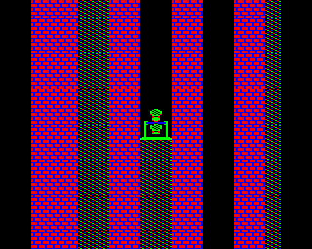
Re: Enhanced mode 1 pictures
It's like the magenta in this screenshot. Spoiler: there's no magenta.VectorEyes wrote: ↑Sun Feb 07, 2021 11:23 pm Ahah, well, take a look at this image, which I generated while I was experimenting with MODE1 dithering and prototyping stuff for a previous Bitshifters demo. If anyone thinks they can see an offyellow ring or two in the image ... so can I. But if you look closer, there are no yellow pixels, only white, cyan and green (and of course black).
Re: Enhanced mode 1 pictures
Sorry, late to this party...
I've been hacking the palette register liberally, albeit only through emulators. I read here that some folks experience speckling on certain real Beebs, though not Masters. The conclusion seems to be that partially programmed palettes won't give un-speckly pictures on a Beeb. However, I think it depends on which revision of the VidProc is present in the machine.
The original was obviously the Ferranti ULA but from what I can tell there were two later version of the VidProc, which were sourced elsewhere and were not ULAs, though the term 'VideoULA' stuck. Reference: https://beebwiki.mdfs.net/Video_ULA
Theory: VidProc part ULA 5C094 is the one that produces the speckling due to that undefined bit that gets shifted in when forming the nibble address into the palette memory. Part VC 2023... don't know... worth checking, perhaps! Part VC 2069, however, I think was the VidProc used in the latter Beebs (rev 7 motherboards?) and the Masters. Therefore, any Beeb with the VC 2069 VidProc will support partially programmed palettes without speckling.