
Hi folks. Sorry for the dumb question again!
If I want to use the AtoMMC part of my combined Econet / AtoMMC board (the AtoMMC part of my board is exactly the same as the latest V4 board by Roland) without a YARRB, I understand I need to burn an A000 version of the ROM into a TMS2532 ROM, and plug that into the socket marked IC24 on the Atom. Is that correct?
Is this the latest A000 release I should be using?
https://github.com/hoglet67/AtoMMC2/rel ... tommc_3_02
Thanks!
Latest A000 version of AtoMMC

Re: Latest A000 version of AtoMMC
Thank you. I've got some 2532 EPROMs on order, so I'll now just need to convince my TL866II programmer to program the EPROM by supplying an external voltage to the programming pin, and also by swapping a couple of pins around to make it look like a 2732!
Re: Latest A000 version of AtoMMC
Right, I received some TMS2532JL-45 EPROMS today, but I'm struggling to program them. I've tried to program with both TL-866II and Genius G540. Neither programmer natively supports the 2532, so I've been hacking a bit to try and get the EPROM to appear as a 2732 to the programmer. I've basically used a couple of sockets to get me this:
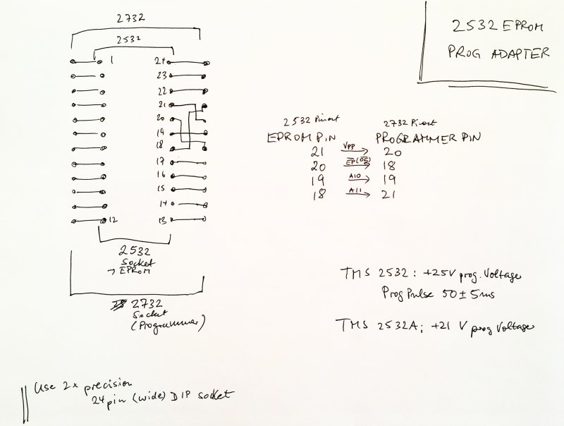
Then firstly on my TL-866II, I followed this guide, and I tried to apply an external +25v to EPROM pin 21 (disconnected from programmer), with a common Gnd on pin 12. This is because the TL-822II can only supply a maximum of 18v:
https://www.youtube.com/watch?v=VwxCpSt-3RQ
However, with the external PSU connected, the programmer came back with a lot of pin errors. Switching off the PSU, the only pin error I got was on the programming pin, which is what I was expecting. Anyway, powered on the PSU again, ignored pin errors, and tried programming, but it came back with a programming / verify error on the first byte. I tried a second EPROM, and got the same error.
So I then went searching, dug out, and tried my G540. This time I connected EPROM pin 21 to pin 20 of the programmer (not sure if the programmer can actually supply the necessary 25v). The programmer reported a faulty pin 20 (programming pin). I went back to my first EPROM and plugged it in. I got the same faulty pin message. I tried a third new EPROM. This time I didn't get any pin errors. However, programming didn't work either.
So, my conclusion is:
Thanks!
Then firstly on my TL-866II, I followed this guide, and I tried to apply an external +25v to EPROM pin 21 (disconnected from programmer), with a common Gnd on pin 12. This is because the TL-822II can only supply a maximum of 18v:
https://www.youtube.com/watch?v=VwxCpSt-3RQ
However, with the external PSU connected, the programmer came back with a lot of pin errors. Switching off the PSU, the only pin error I got was on the programming pin, which is what I was expecting. Anyway, powered on the PSU again, ignored pin errors, and tried programming, but it came back with a programming / verify error on the first byte. I tried a second EPROM, and got the same error.
So I then went searching, dug out, and tried my G540. This time I connected EPROM pin 21 to pin 20 of the programmer (not sure if the programmer can actually supply the necessary 25v). The programmer reported a faulty pin 20 (programming pin). I went back to my first EPROM and plugged it in. I got the same faulty pin message. I tried a third new EPROM. This time I didn't get any pin errors. However, programming didn't work either.
So, my conclusion is:
- I think I've damaged my first two EPROMs by applying an external 25v to pin 21 of the 2532 when trying to program in my TL-866II. I'm hesitant to do that any more.
- I suspect I don't have sufficient voltage on my G540 to program the 2532.
Thanks!
Re: Latest A000 version of AtoMMC
I can guarantee a G540 won't program a 2532, because it can't supply 25V at sufficient current. Mine won't even program 21V devices.
Where did you purchase the devices? Is it possible they are remarked? Do all three parts look identical? Remarking 2732A as 2532A is not uncommon. I have a tube of these! Post a photo please.
You might be able to tell a remared part by measuring the DC resistance of the input pins to GND. All address inputs should have the same resistance. The absolute value is may depend on your meter, but the PGM pin (either 20 or 21) will be a bit lower. On a genuine 2532A I measured the address lines at 5.87KB. The PGM pin is a bit lower at 4.87KB.
Reading the data sheet, VPP must only be applied when VCC is at 5V and stable. If the programmer is also controlling VCC, then it's possible the devices were damaged.
So you probably want to manually control both VCC and VPP and be careful about sequencing.
You could also put one of the possibly broken devices into a bread board, power VCC and VPP from a bench power supply, and measure the current draw on VCC and VPP. Again, only apply +25V to VPP when VCC is +5V.
VPP should draw max of 30mA.
BTW, if they were remarked 2732As then they will likely have been damaged by applyng VPP to the "wrong" pin.
Dave
Re: Latest A000 version of AtoMMC
They came from China via AliExpress, but they look pretty genuine. It's actually very difficult to see the marking on the ICs, but under strong light, and holding at a very specific angle you can read the markings.hoglet wrote: ↑Fri Apr 21, 2023 5:17 pm I can guarantee a G540 won't program a 2532, because it can't supply 25V at sufficient current. Mine won't even program 21V devices.
Where did you purchase the devices? Is it possible they are remarked? Do all three parts look identical? Remarking 2732A as 2532A is not uncommon. I have a tube of these! Post a photo please.
I did have a quick read through the datasheet, but obviously missed that critical part. I suspect this is where I've gone wrong with the first two EPROMs. I'll do some further resistance checks to compare with your observations. I did wonder why there was a 'VDD Write' setting in the programming software, which is typically set to 5v.
Re: Latest A000 version of AtoMMC
Ok, so I've tried again this morning, taking manual control of both Vcc and Vpp, but still can't get this to work on either programmer.
The TL-866II programmer certainly seems happier now that I'm sequencing the power up of Vcc and Vpp (not getting all the pin fail errors I was seeing before, and I don't seem to be damaging the ICs either now). However, it's still failing to write.
I'm starting to think that perhaps my 2532s aren't what they claim to be.
On one of my remaining 'good' ICs I've taken some resistance measurements:
The other thing I've noticed with these ICs is that erase window is flush with the top of the IC. Other photos of 2532s (and the original IC I got with my AtoMMC) have a slightly raised window. I wonder if that's also telling me something!?
The TL-866II programmer certainly seems happier now that I'm sequencing the power up of Vcc and Vpp (not getting all the pin fail errors I was seeing before, and I don't seem to be damaging the ICs either now). However, it's still failing to write.
I'm starting to think that perhaps my 2532s aren't what they claim to be.
On one of my remaining 'good' ICs I've taken some resistance measurements:
- The address pins (1,2,3,4,5,6,7,8,18,19,22,23) all measure about 3.8MOhm.
- The data pins (9,10,11,13,14,15,16,17) all measure about 3.3MOhm
- Pin 20 measures about 3MOhm
- Pin 21 measures the same as the address pins at about 3.8MOhm
The other thing I've noticed with these ICs is that erase window is flush with the top of the IC. Other photos of 2532s (and the original IC I got with my AtoMMC) have a slightly raised window. I wonder if that's also telling me something!?
Re: Latest A000 version of AtoMMC
I get open circuit if I reverse the probes. It actually threw me for a minute, because I was measuring resistance on the first attempt, but not on the second attempt. I then figured out the probe polarity was having an impact.
Re: Latest A000 version of AtoMMC
Why not try programming one as a 2732 @ 21V?
I think genuine TMS2532/TMS2532A do have the raised windows - this is clearly visible on the datasheet.
So this does suggest your flat topped TMS2532A are likely fake.
Unfortunately, a lot of older EPROMs also have the raised windows, so this alone is not a guarantee.
Also, while the TMS2532 needs 25V for programming, apparently the TMS2532A only needs 21V. I haven't managed to find a data sheet to confirm this though!
Dave
Re: Latest A000 version of AtoMMC
And a follow on question...KenLowe wrote: ↑Tue Apr 04, 2023 8:46 pm Hi folks. Sorry for the dumb question again!
If I want to use the AtoMMC part of my combined Econet / AtoMMC board (the AtoMMC part of my board is exactly the same as the latest V4 board by Roland) without a YARRB, I understand I need to burn an A000 version of the ROM into a TMS2532 ROM, and plug that into the socket marked IC24 on the Atom. Is that correct?
Is this the latest A000 release I should be using?
https://github.com/hoglet67/AtoMMC2/rel ... tommc_3_02
Thanks!
If I didn't have a YARRB (or any other mods) in my Atom, is it possible to have both the AtoMMC ROM and the patched NFS ROM installed at the same time? It looks like IC24 @ #A000 is the only slot available, so I would need to swap out the ROMs to switch between AtoMMC & NFS. Is that correct?
Re: Latest A000 version of AtoMMC
BITD I soldered two 2532 EPROMS on top of each other (piggy-packing) except for the chip enable pin (20). I got CS#Exxx from pin 9 of IC23 and connected that to pin 20 of the top EPROM. To avoid a bus conflict bent out pin 4 of IC8 and connect it to +5V through a 4k7 resistor. You can run AtoMMC at #Exxx and Econet at #Axxx with this setup.
FPGAtom: 512 KB RAM, Real Time Clock and 64 colours
MAN WOMAN
MAN WOMAN
Re: Latest A000 version of AtoMMC
Thank you. That's very helpful. I'm not sure how important it is, but hoglet built my YARBB ROM with the patched Econet ROM at #A000 and AtoMMC at #E000, so that's what I was hoping to try and replicate without YARBB. I'm thinking that should be easy to implement, by just switching the ROMs around:
Regarding the piggy backed ROMs, what I might do is make a small PCB with a more readily available 2764 (or larger) EPROM. I'd need to take #A000 and #E000 through an AND gate, and take the output of that to the 2764 chip enable (or possibly the OE) pin. I'd also need to wire #A000 (or #E000) to A12 on the 2764 and use that to switch in the correct bank. Obviously still need to do the mod at IC8 pin 4.
I made a start to swapping out the 2532 with a different IC here. I'd just look to modify that:
viewtopic.php?t=28136
With that ROM arrangement in my YARRB, I use ?#BFFE=2 / ?#BFFE=6 to switch between AtoMMC & Econet. How would that work with a 2764 ROM and no YARRB???
Regarding the piggy backed ROMs, what I might do is make a small PCB with a more readily available 2764 (or larger) EPROM. I'd need to take #A000 and #E000 through an AND gate, and take the output of that to the 2764 chip enable (or possibly the OE) pin. I'd also need to wire #A000 (or #E000) to A12 on the 2764 and use that to switch in the correct bank. Obviously still need to do the mod at IC8 pin 4.
I made a start to swapping out the 2532 with a different IC here. I'd just look to modify that:
viewtopic.php?t=28136
Re: Latest A000 version of AtoMMC
That's switching the ROM set that appears at #C000-#FFFF:
- Rom set 0 contains an #E000 version of AtoMMC
- Rom set 1 contains an #E000 version of DOS ROM
Without YARRB you'll need a different plan.
Maybe some experimentation / prototyping is required before you commit to a PCB...
The easier solution using a 2764, is to allow for two ROMs at #E000 with a physical switch to select between them. Then use the #E000 verions of both AtoMMC and Econet 350.
If you used a 27128, then there would also be space for a Utility ROM at #A000.
Dave
Re: Latest A000 version of AtoMMC
Thanks Dave. That's confirmed what I suspected.
I wonder if the simplest solution here is to go for the YARRB-M2. According to the manual, you can switch in different ROMs at #E000 (we could swap out DOS for Econet):
Or perhaps we can have the same ROM configuration in YARRB-M2 as we have in earlier YARRB & YARRB-2, with patched Econet ROM in #A000 ROM 0 and AtoMMC in #E000? What happens if you've got both ROMs in the memory map at the same time? Does one File System ROM take priority over the other?
I wonder if the simplest solution here is to go for the YARRB-M2. According to the manual, you can switch in different ROMs at #E000 (we could swap out DOS for Econet):
The only potential issue I can see is that #0A00..#0AFF will be disabled when bit 2 of #BFFE is set high. But that's perhaps how the original YARBBs work, so possibly not an issue.YARRB-M2 wrote:Code: Select all
BFFE: bit 2 MMC/DOS mode (0 = MMC, 1 = DOS)

In DOS mode, an alternative ROM image is selected at block #Exxx and the RAM is disabled from
#0A00 - #0AFF, allowing a factory default floppy disc controller can be attached to the Atom. The
CPLD takes care of driving the data bus buffer. This buffer is also enabled when accessing the I/O
space from #BC00 - #BFFF.
Or perhaps we can have the same ROM configuration in YARRB-M2 as we have in earlier YARRB & YARRB-2, with patched Econet ROM in #A000 ROM 0 and AtoMMC in #E000? What happens if you've got both ROMs in the memory map at the same time? Does one File System ROM take priority over the other?
Re: Latest A000 version of AtoMMC
That's different the original YARRB:
I'm sure you could tweak the CPLD to leave #A00-#AFF as RAM all the time (or ask Roland nicely)
The #A000 ROM only runs if you configure the auto boot interrnel (and fit LK3), or if you LINK the manual initialization address.KenLowe wrote: ↑Fri Dec 22, 2023 11:50 pm Or perhaps we can have the same ROM configuration in YARRB-M2 as we have in earlier YARRB & YARRB-2, with patched Econet ROM in #A000 ROM 0 and AtoMMC in #E000? What happens if you've got both ROMs in the memory map at the same time? Does one File System ROM take priority over the other?
Dave
Re: Latest A000 version of AtoMMC
Thanks Dave, I did eventually figure this out myself yesterday.
Yup, I did wonder about that.
So, this is where I'm getting a bit confused...hoglet wrote: ↑Sat Dec 23, 2023 8:09 amThe #A000 ROM only runs if you configure the auto boot interrnel (and fit LK3), or if you LINK the manual initialization address.KenLowe wrote: ↑Fri Dec 22, 2023 11:50 pm Or perhaps we can have the same ROM configuration in YARRB-M2 as we have in earlier YARRB & YARRB-2, with patched Econet ROM in #A000 ROM 0 and AtoMMC in #E000? What happens if you've got both ROMs in the memory map at the same time? Does one File System ROM take priority over the other?
With my YARRB / YARRB-2 and the custom ROM image we developed:
I am using ?#BFFE=2 / ?#BFFE=6 to switch between AtoMMC & Econet. From what I understand this is doing the #C000..#FFFF bank switching via bit 2 and mapping in the RAM at #A00-#AFF via bit 1, so basically moving a different file system ROM into #E000. In my case, this would be either AtoMMC or Atom DOS? I do also have LK3 made, so the Econet ROM at #A000 also being initialised? So, what's stopping both AtoMMC and Econet from being active at the same time when I've switched AtoMMC into #E000?
Edit: Ah. I've just realised that you then provided me with an #E000 version of Econet, which I assume replaces Atom DOS:
viewtopic.php?p=379549#p379549
...everything is starting to become a bit clearer. And because we've ditched Atom DOS, there's no longer a need to map out the RAM at #0A00..#0AFF with either AtoMMC or Econet; hence the suggestion to have a custom version of YARRB-M2 created.
Re: Latest A000 version of AtoMMC
I'm not sure that setup would be reliable. When you have AtoMMC at #E000 and Econet at #A000 with LK3 made, you probably end up with a bit of a race condition, depending on exactly when the PL8 interrupt happens. Which ever file system happens to be initialized last will "win". I don't think I have ever tried it.KenLowe wrote: ↑Sat Dec 23, 2023 9:34 am I am using ?#BFFE=2 / ?#BFFE=6 to switch between AtoMMC & Econet. From what I understand this is doing the #C000..#FFFF bank switching via bit 2 and mapping in the RAM at #A00-#AFF via bit 1, so basically moving a different file system ROM into #E000. In my case, this would be either AtoMMC or Atom DOS? I do also have LK3 made, so the Econet ROM at #A000 also being initialised? So, what's stopping both AtoMMC and Econet from being active at the same time when I've switched AtoMMC into #E000?
That makes much more sense and is the configuration I'm running.KenLowe wrote: ↑Sat Dec 23, 2023 9:34 am Edit: Ah. I've just realised that you then provided me with an #E000 version of Econet, which I assume replaces Atom DOS:
viewtopic.php?p=379549#p379549
The only issue is when using Econet like this, you loose the BRAN automatic #A000 ROM switching, because the BRAN code sits at the end of the AtoMMC ROM. Back in the day there was a #1000 version of BRAN, but that would now conflict with much of the modern atom software. So when you use Econet, you are limited to manual #A000 ROM switching using ?#BFFF=N.
Dave
Last edited by hoglet on Sat Dec 23, 2023 10:16 am, edited 1 time in total.
Re: Latest A000 version of AtoMMC
There's still a bit (3) free in #BFFE so I can use that to select RAM or nothing at #A00. So for Econet you can select the second ROM bank and still have RAM at #A00. I'll have a go at this.
FPGAtom: 512 KB RAM, Real Time Clock and 64 colours
MAN WOMAN
MAN WOMAN
Re: Latest A000 version of AtoMMC
I think I have it working now:
This is in MMC mode (default):
And this is in DOS mode (you can replace the DOSROM by Econet):
I discovered an undocumented feature in my VHDL code: BFFE(3) was used to write protect #1000 - #1FFF for DOS configurations with Branquar at #1000. I moved this control bit to BFFF(3) and that seems to work fine, although a bit tweaking with the shadow byte at #FD is needed.
So the new configuration bits are:
BFFF 0 ... 2: bank select #Axxx block
BFFF 3: write enable (0) or disable (1) for #1xxx block
BFFE 0: clock select (0 = 1MHz, 1 = 2MHz)
BFFE 1: Turbo mode (4MHz, regardless of bit 0)
BFFE 2: ROM Bank select (0 = AtoMMC, 1 = Atom DOS or Econet)
BFFE 3: RAM #A00 - #AFF enabled (0) or disabled(1)
So for working with Atom DOS you should use ?#BFFE=12 and for Econet ?#BFFE=8 will do.
Does that solve your problems?
This is in MMC mode (default):
So the new configuration bits are:
BFFF 0 ... 2: bank select #Axxx block
BFFF 3: write enable (0) or disable (1) for #1xxx block
BFFE 0: clock select (0 = 1MHz, 1 = 2MHz)
BFFE 1: Turbo mode (4MHz, regardless of bit 0)
BFFE 2: ROM Bank select (0 = AtoMMC, 1 = Atom DOS or Econet)
BFFE 3: RAM #A00 - #AFF enabled (0) or disabled(1)
So for working with Atom DOS you should use ?#BFFE=12 and for Econet ?#BFFE=8 will do.
Does that solve your problems?
FPGAtom: 512 KB RAM, Real Time Clock and 64 colours
MAN WOMAN
MAN WOMAN
Re: Latest A000 version of AtoMMC
That looks perfect, thank you! But, based on your table, I think the selection would be...roland wrote: ↑Sat Dec 23, 2023 12:11 pm I think I have it working now:
This is in MMC mode (default):
And this is in DOS mode (you can replace the DOSROM by Econet):
I discovered an undocumented feature in my VHDL code: BFFE(3) was used to write protect #1000 - #1FFF for DOS configurations with Branquar at #1000. I moved this control bit to BFFF(3) and that seems to work fine, although a bit tweaking with the shadow byte at #FD is needed.
So the new configuration bits are:
BFFF 0 ... 2: bank select #Axxx block
BFFF 3: write enable (0) or disable (1) for #1xxx block
BFFE 0: clock select (0 = 1MHz, 1 = 2MHz)
BFFE 1: Turbo mode (4MHz, regardless of bit 0)
BFFE 2: ROM Bank select (0 = AtoMMC, 1 = Atom DOS or Econet)
BFFE 3: RAM #A00 - #AFF enabled (0) or disabled(1)
So for working with Atom DOS you should use ?#BFFE=12 and for Econet ?#BFFE=8 will do.
Does that solve your problems?
Atom DOS: ?#BFFE=12
AtoMMC: ?#BFFE=0 (Edit: Corrected. I previously suggested the register should be set to 8, which would incorrectly disable the RAM at #A00 - #AFF. It only needs to be disabled for DOS)
Econet: ?#BFFE=4
Last edited by KenLowe on Thu Feb 29, 2024 12:14 am, edited 1 time in total.
Re: Latest A000 version of AtoMMC
So, one final question...
Would the YARRB image that @holget posted here be compatible with this YARBB-M2, or would we need to create a different one for YARRB-M2?
Would the YARRB image that @holget posted here be compatible with this YARBB-M2, or would we need to create a different one for YARRB-M2?
Re: Latest A000 version of AtoMMC
Those ROMS are not identical and cannot be interchanged. But it's easy to create an Econet version of the ROM when I have the Econet ROM image.
FPGAtom: 512 KB RAM, Real Time Clock and 64 colours
MAN WOMAN
MAN WOMAN
Re: Latest A000 version of AtoMMC
Sorry for the delay in replying. Laptop has been packed away from Christmas! Thanks for confirming the ROMs are not interchangeable. An updated ROM would be ideal, but there's no rush for this. I'll be back in touch when I'm ready to go.
Thanks.
Thanks.